

6th-Jan-25, 12:13 PM
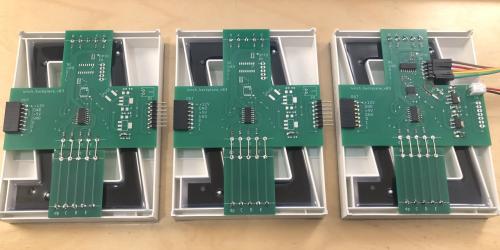
The first photo shows three of the ‘modular’ 4 inch 7 segment displays as required for the speed trap project.
The module on the right has the data digital inputs and the 15V power supply input.
The data digital inputs are wired via a quad opto isolator followed by digital inverters.
The 15V input feeds into a 12V regulator which drives the common anode LED display modules. The 12V regulator in turn feeds into a 5V regulator which drives the digital logic.
The other two modules shown don’t require this additional circuitry.
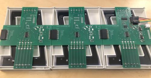
This second photo shows the three modules connected together via their male and female headers.
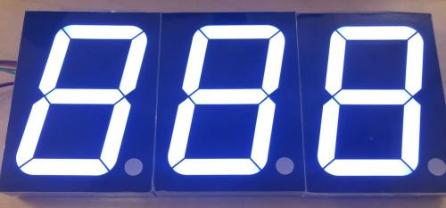
The third photo shows the same three display modules displaying ‘888’ as generated by a nearby microcontroller.
Next, some additional display modules to be added and some track sensors to drive the timing firmware inside the microcontroller.
:)
c
The module on the right has the data digital inputs and the 15V power supply input.
The data digital inputs are wired via a quad opto isolator followed by digital inverters.
The 15V input feeds into a 12V regulator which drives the common anode LED display modules. The 12V regulator in turn feeds into a 5V regulator which drives the digital logic.
The other two modules shown don’t require this additional circuitry.
This second photo shows the three modules connected together via their male and female headers.
The third photo shows the same three display modules displaying ‘888’ as generated by a nearby microcontroller.
Next, some additional display modules to be added and some track sensors to drive the timing firmware inside the microcontroller.
:)
c
