Posts: 4,528
Threads: 147
Likes Received: 3,066 in 1,819 posts
Likes Given: 4,215
Joined: Apr 2019
Location Isle of Man
Sensored BL RC motors...
ESC, yes most probably as we never had to faff about changing anything else to reverse direction other than two wire swap.
Life is like a box of Slot cars...


Posts: 334
Threads: 25
Likes Received: 596 in 255 posts
Likes Given: 143
Joined: Oct 2023
@Kevan et al.,
There is a very nice section in the Texas Instruments manual for the IC I am using which explains how to match correctly each of the three Hall sensor IC outputs with the corresponding coil winding. It does require a four channel oscilloscope but looks to ‘be faff-free’, though fairly technical.
Meanwhile in the world of digital slotcars things are nice and simple. AW and SW always are required to run in one direction (this is not universally true as per Kevan’s post below - thanks) and for in-line, direction depends on which side the crown gear is located. So two versions of the drive board required, one for clockwise and one for counter-clockwise rotation.
Anyway, I’m running ahead of myself here, seeing the new driver modules running motors in cars on tracks is a more immediate objective :)
c
(This post was last modified: 10th-Aug-25, 01:00 PM by
Dr_C2.)
 •
Posts: 4,528
Threads: 147
Likes Received: 3,066 in 1,819 posts
Likes Given: 4,215
Joined: Apr 2019
Location Isle of Man
SW and AW run in either direction also depending which side the spur gear is on.
Life is like a box of Slot cars...
Posts: 334
Threads: 25
Likes Received: 596 in 255 posts
Likes Given: 143
Joined: Oct 2023
(10th-Aug-25, 12:45 PM)Kevan Wrote: SW and AW run in either direction also depending which side the spur gear is on.
Thanks Kevan for the correction! I’ve clearly spent too long looking at NSR motor mounts :)
Posts: 334
Threads: 25
Likes Received: 596 in 255 posts
Likes Given: 143
Joined: Oct 2023
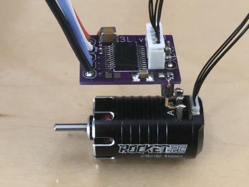
Here is the driver module sitting on top of the motor.
The driver module will sit closer to the motor for vehicle installs perhaps 1-2mm separation.
The thin black wires connect to the three Hall sensor ICs inside the motor. At the moment I am using plug connections for simplicity - however for vehicle installs the large (relatively speaking) white JST plug can be replaced with direct wire-to-pcb soldering to save space. And far shorter black wiring too.
c
(This post was last modified: 10th-Aug-25, 01:25 PM by
Dr_C2.)
Posts: 4,528
Threads: 147
Likes Received: 3,066 in 1,819 posts
Likes Given: 4,215
Joined: Apr 2019
Location Isle of Man
That's a really nice looking unit

Life is like a box of Slot cars...
Posts: 59
Threads: 6
Likes Received: 79 in 38 posts
Likes Given: 74
Joined: Nov 2023
It always amazes me how they make electronics so small, especially looking at those Sensored motors.
Posts: 334
Threads: 25
Likes Received: 596 in 255 posts
Likes Given: 143
Joined: Oct 2023
(11th-Aug-25, 05:12 AM)Drifter2 Wrote: It always amazes me how they make electronics so small, especially looking at those Sensored motors.
100% agree :)
•
Posts: 334
Threads: 25
Likes Received: 596 in 255 posts
Likes Given: 143
Joined: Oct 2023
From inspection, the three Hall sensor ICs are located on a ‘doughnut’ shaped pcb with each IC at 120degrees with respect to its neighbours either side. This whole electronics assembly occupies the last 5mm, only, of the 25mm motor body casting.
c
Posts: 334
Threads: 25
Likes Received: 596 in 255 posts
Likes Given: 143
Joined: Oct 2023
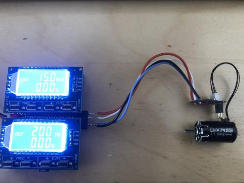
Here is the SENSORED brushless motor and piggy-back drive module connected to two PWM signal generators.
The motor drive PWM is set to 15kHz as per the Texas Instruments datasheet.
The brake circuit PWM is set to 200Hz - a much lower frequency since the datasheet doesn’t specify the permitted bandwidth of this input.
The dual PWM assembly includes a brake activation button.
Previously I reported the brushless motor and experimental drive module function correctly in terms of motor drive.
I am pleased to report, now, that the brake circuits are functioning correctly too.
This completes bench level testing. Next up, will be the installation into NSR AMG and NSR F1 chassis.
Surprisingly - all continues to go perfectly to plan. Long may this continue :)
c
(This post was last modified: 14th-Aug-25, 01:45 PM by
Dr_C2.)


