

7th-Apr-24, 06:19 PM
System testing of the Smart LEDs continues on a number of digital racetracks in a number of countries.
The photo below shows Smart LEDs which can be interfaced with standard oXigen decoders in order to generate a range of ‘SSD-style’ IDs in the range 1 to 36.
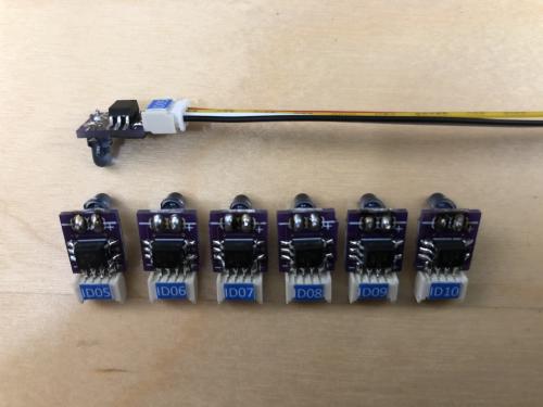
Each Smart LED is pre-flashed to a specific ID. Hence in the photo each Smart LED has a blue label showing the ID in use.
The Smart LED includes a standard 3mm IR LED and has a four pin JST connector.
The four JST connections are:
Red: +3.3V from decoder
Yellow: Expernal LED+ (A) round LED pad on decoder
White: External LED - (K) square LED pad on decoder
Black: 0V from decoder
The Smart LED reads the staystraight/lanechange signal from the decoder (on any ID) and translates the output strobe signal to the pre-flashed ID. As mentioned this can be any value in the range ID1 to ID36. As per the Scalextric protocol, inversion of the mark-to-space ratio is used to indicate a lane change request.
For anyone involved in trials of the Smart LEDs I will share a simple wiring diagram showing how to connect the Smart LEDs to commercial in-market decoders.
The Smart LEDs can be used with any decoder brand which generates a SSD conpatible IR LED strobe signal. The Smart LEDs shown are designed for use with 3.3V decoders, though earlier versions were tested with 5V decoders.
In the future, and once fully proven, the 36 car ID method may be integrated directly into the main microcontroller within the decoder.
c
The photo below shows Smart LEDs which can be interfaced with standard oXigen decoders in order to generate a range of ‘SSD-style’ IDs in the range 1 to 36.
Each Smart LED is pre-flashed to a specific ID. Hence in the photo each Smart LED has a blue label showing the ID in use.
The Smart LED includes a standard 3mm IR LED and has a four pin JST connector.
The four JST connections are:
Red: +3.3V from decoder
Yellow: Expernal LED+ (A) round LED pad on decoder
White: External LED - (K) square LED pad on decoder
Black: 0V from decoder
The Smart LED reads the staystraight/lanechange signal from the decoder (on any ID) and translates the output strobe signal to the pre-flashed ID. As mentioned this can be any value in the range ID1 to ID36. As per the Scalextric protocol, inversion of the mark-to-space ratio is used to indicate a lane change request.
For anyone involved in trials of the Smart LEDs I will share a simple wiring diagram showing how to connect the Smart LEDs to commercial in-market decoders.
The Smart LEDs can be used with any decoder brand which generates a SSD conpatible IR LED strobe signal. The Smart LEDs shown are designed for use with 3.3V decoders, though earlier versions were tested with 5V decoders.
In the future, and once fully proven, the 36 car ID method may be integrated directly into the main microcontroller within the decoder.
c
