

1st-Dec-23, 10:59 AM
Repair Step 1
==========
Test diodes with a Digital meter (in diode test mode) and replace any that are faulty.
I will discuss diode testing in a future post - basically we set our test meter to ‘diode test mode’ and probe across each of the four diodes in turn. For each diode we check with the leads in each polarity. In the forward direction the meter should read in the range 0.2-0.7 Volts. In the reverse direction the meter should read infinite Ohms or there abouts. If any of the diodes give an anomalous reading remove from the board, test again and if necessary replace with a new one.
Repair Step 2
==========
Remove both output MOSFETs and replace only the n-channel MOTOR drive MOSFET with a new one. This is the MOSFET labelled N02 on the rev G decoder board.
Please click on photos for a full frame and full resolution image.
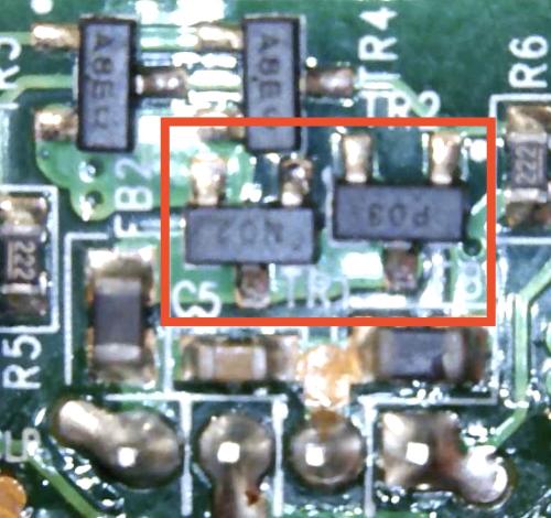
Photo: The two MOSFETs which are to be removed.
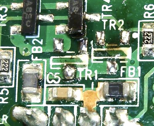
Photo: After removal and pad clean-up.
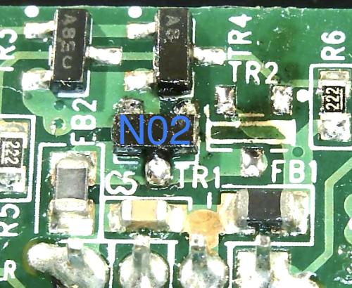
Photo: N02 refitted (This should be a new replacement part).
Repair Step 3
==========
If the decoder then functions, i.e. motor is controllable, then replace the p-channel MOSFET. This is the one labelled P03 on the rev G decoder board.
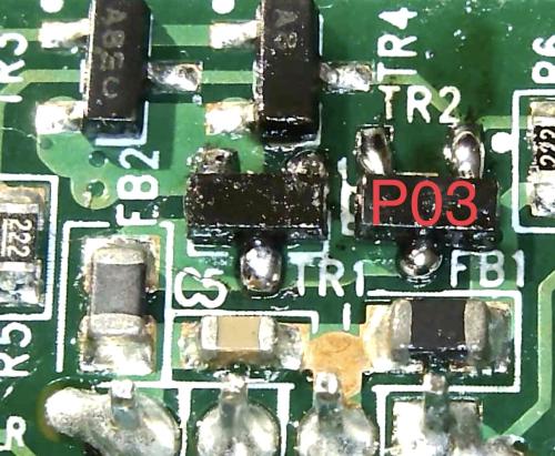
Photo: P03 refitted. Again, this should be a new replacement part.
Follow-on
=======
If the decoder then functions i.e. motor and brake are controllable the job is done. If not a more advanced diagnostic is required.
==========
Test diodes with a Digital meter (in diode test mode) and replace any that are faulty.
I will discuss diode testing in a future post - basically we set our test meter to ‘diode test mode’ and probe across each of the four diodes in turn. For each diode we check with the leads in each polarity. In the forward direction the meter should read in the range 0.2-0.7 Volts. In the reverse direction the meter should read infinite Ohms or there abouts. If any of the diodes give an anomalous reading remove from the board, test again and if necessary replace with a new one.
Repair Step 2
==========
Remove both output MOSFETs and replace only the n-channel MOTOR drive MOSFET with a new one. This is the MOSFET labelled N02 on the rev G decoder board.
Please click on photos for a full frame and full resolution image.
Photo: The two MOSFETs which are to be removed.
Photo: After removal and pad clean-up.
Photo: N02 refitted (This should be a new replacement part).
Repair Step 3
==========
If the decoder then functions, i.e. motor is controllable, then replace the p-channel MOSFET. This is the one labelled P03 on the rev G decoder board.
Photo: P03 refitted. Again, this should be a new replacement part.
Follow-on
=======
If the decoder then functions i.e. motor and brake are controllable the job is done. If not a more advanced diagnostic is required.
