Posts: 334
Threads: 25
Likes Received: 596 in 255 posts
Likes Given: 143
Joined: Oct 2023
Three PCBs designed ready for the sensored brushless slotcar trials:
1/ A new DPR sized core microcontroller board with 5 pin interface. This is designed for SSD and includes lighting circuits.
2/ A relatively small sensored brushless driver module which will piggy-back onto the brushless motor. This of course has the same 5 pin interface as the above board.
3/ A simple 8 LED diagnostic board which optionally connects onto the driver module. This is designed to display various status information as the Texas Instruments driver module is being configured.
The 5 pin interface used to be described as a 4 pin interface but I added one extra signal… the tacho return signal!
Now the wait until the boards are manufactured :)
Thanks for your interest.
c
(This post was last modified: 19th-Jul-25, 05:10 PM by
Dr_C2.)
 •
Posts: 334
Threads: 25
Likes Received: 596 in 255 posts
Likes Given: 143
Joined: Oct 2023
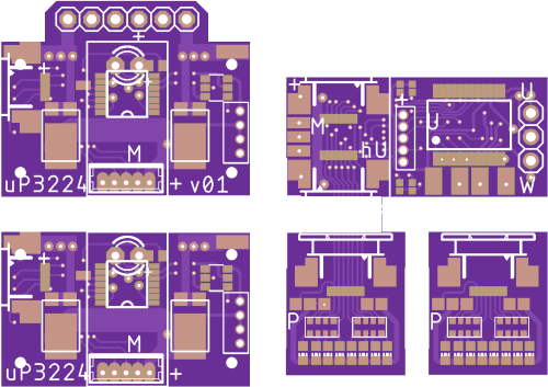
Here is the set of recently designed PCBs for the sensored brushless slotcar project. They should arrive in 7-10 days.
The photo shows in order clockwise from bottom left:
1/ The DPR sized SSD microcontroller core which includes IR LED, front/rear lighting socket, windscreen display interface socket, and the 5-pin socket that connects to the motor. The microcontroller is coded in C++.
2/ This is the same DPR sized SSD microcontroller core as above but with a six way IDE header for direct mounting onto my NSR test cars which have a matching socket.
3/ This PCB is the experimental sensored brushless motor DRIVER MODULE. It is a complete evaluation board with some extra interface ports for system optimisation. The five-pin socket towards the centre of the board is for the three Hall sensors. This is a motor piggy-back design. The final design will be significantly smaller once those extra interface ports are no longer required and can be removed. The design point has already been tested using a manufacturers full size evaluation board - so next steps should progress swiftly (hopefully!).
4&5/ These are the optional LED displays - purely a diagnostic tool for use during system development.
These components represent a fun brushless motor ‘sand pit’.
Thanks for reading.
c
(This post was last modified: 20th-Jul-25, 09:25 AM by
Dr_C2.)
•
Posts: 334
Threads: 25
Likes Received: 596 in 255 posts
Likes Given: 143
Joined: Oct 2023
While I wait for the above PCBs to be delivered, I’ve been preparing the final format of the piggy-back sensored brushless motor driver MODULE. I won’t commit this to manufacture until the above PCBs have been tested - just in case anything needs to be tweaked ;)
The later module measures approximately 15mm x 20mm and so should fit perfectly piggy-backed over the brushless motors which I have chosen which have a diameter of 15mm and a length of 25mm.
Next I will be looking at physical fit of the sensored brushless motors and matching modules into the following three NSR motor pods/cars:
1/ In-line pod for NSR F1 86/89.
2/ In-line pod for NSR F1 22
3/ AW pod for NSR Z4 and AMG etc.
Again, thanks for your interest - and without doubt what I am attempting will become far clearer when I share some photographs :)
c
(This post was last modified: 24th-Jul-25, 01:34 PM by
Dr_C2.)
Posts: 334
Threads: 25
Likes Received: 596 in 255 posts
Likes Given: 143
Joined: Oct 2023
Hi all,
… a quick high-level overview of what I have been learning about brushless (BL) motors for DIGITAL slot-cars since I started exploring this opportunity a few years back. It’s a collective effort so thanks to others too!
1/ A few years back I played with UNSENSORED brushless motors and got as far as driving an SSD controlled slot-car around a track using a very basic TI driver IC to control a 6800Kv brushless motor fitted to a Slot.it motor pod. As an initial trial it was a success - but there were two obvious weaknesses - first: there were no brakes and second: there was a severe ‘cogging’ effect at low throttles.
For me the latter pointed to the need to use SENSORED brushless motors if low speed control is to be desired. This of course is my personal opinion based on my fairly limited experience - so I may well be proven wrong in due course ;)
2/ the above sets the scene for this thread… it’s all about SENSORED brushless motors and their control.
3/ I’m now using a range of SENSORED brushless motors which fit nicely into NSR motor pods without any adapters. They range from 3500Kv to 6800Kv … so lots of options.
4/ I’ve been using a Texas Instruments development board to drive SENSORED motors at their rated rpm. These motors start-up very smoothly and are smoothly controllable to their rated rpm. Importantly there is no observable ‘cogging’ and dynamic braking appears to function correctly.
5/ But… the Texas Instruments development board I am using is far too large to fit into a digital slotcar. That explains the new PCBs I am having manufactured. These boards use the same circuits as per the development boards but in a format which fits inside DIGITAL slotcats. The fact the boards can piggy-back onto the motors is a nice-to-have, but what is most important is that the new PCBs provide a route to track level trials.
If you are interested in DIGITAL BRUSHLESS slot-cars please keep watching this space. It all appears to be going to plan!
c
(This post was last modified: 24th-Jul-25, 10:05 PM by
Dr_C2.)
Posts: 334
Threads: 25
Likes Received: 596 in 255 posts
Likes Given: 143
Joined: Oct 2023
Two small observations/corrections…
1/ I’m not sure the meaning of the term ‘slotcat’ as it appears in my previous post.
2/ I forgot to mention in the above summary that before progressing intensively with the SENSORED brushless project I did run some laps with an NSR slotcar equipped with a sensored brushless motor which was controlled by a RC receiver and a RC electronic speed controller. It drove smoothly at low, medium and high speeds. This added to my confidence that SENSORED is the best way forward for digital slot cars (and of course slotcats if they exist).
The new PCBs arrive early next week.
c
(This post was last modified: 25th-Jul-25, 11:58 AM by
Dr_C2.)
Posts: 4,528
Threads: 147
Likes Received: 3,066 in 1,819 posts
Likes Given: 4,215
Joined: Apr 2019
Location Isle of Man
Slot Cats...not just for Christmas...
Life is like a box of Slot cars...


Posts: 334
Threads: 25
Likes Received: 596 in 255 posts
Likes Given: 143
Joined: Oct 2023
It’s getting exciting (well for me anyway).
The above mentioned new PCBs arrive tomorrow. First up will be to double check that all component positions are correct and that all track connections are correct.
All being well the next step will be assembly of the sensored brushless driver modules. Remember these sit between the digital decoder and the brushless motor.
There are eight assembly options … these consist of three sets of ‘ binary’ options - giving the total of eight combinations:
1/ cw or ccw rotation
2/ wiring as per either variant of the two motor types I am using (both were shown in earlier photos)
3/ then, there are two key versions - one for bespoke brushless decoders and one with an additional interface IC to connect with standard SSD, D132, SCX-A or O2 decoders.
The arrival of these boards is going to occupy a lot of my ‘hobby-time’ over the next few weeks for sure :)
Let’s see if we can nudge forward some useful progress with SENSORED brushless motors for digital slot-cars.
c
(This post was last modified: 27th-Jul-25, 08:23 PM by
Dr_C2.)
Posts: 334
Threads: 25
Likes Received: 596 in 255 posts
Likes Given: 143
Joined: Oct 2023
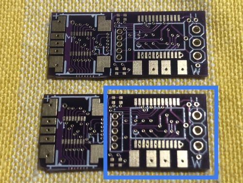
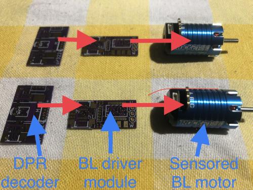
First photo shows the SENSORED brushless driver module. It’s a development board at this stage. The blue box shows the core of the driver board with the additional circuitry to the left providing a diagnostic interface capability. These boards check out correctly and shortly will be populated with components and fitted into digital slot test cars.
The second photo shows the drive components which are required for a GT3 install… a DPR-sized decoder, the driver module and the brushless motor - in this case a 3500Kv variant. The red arrows show the signal path from decoder to motor.
Next, some assembly required ;)
c
(This post was last modified: 28th-Jul-25, 05:47 PM by
Dr_C2.)
Posts: 334
Threads: 25
Likes Received: 596 in 255 posts
Likes Given: 143
Joined: Oct 2023
This SENSORED brushless motor driver module (or electronic commutator or e-com) is the first I have seen which is designed to interface with a digital slot-car decoder and to fit inside a digital slot-car. The design point in terms of circuit detail matches the recommended design point of the semiconductor manufacturer - in this case Texas Instruments - so there is a very high probability this small driver module will successfully integrate with digital slot cars. Of course the proof of the pudding will be in the eating … so let’s see.
c
(This post was last modified: 28th-Jul-25, 06:38 PM by
Dr_C2.)
Posts: 334
Threads: 25
Likes Received: 596 in 255 posts
Likes Given: 143
Joined: Oct 2023
The Texas Instruments evaluation board I have been using to configure and optimise the design of my custom driver modules measures 89mm x 63mm and has numerous jumpers and hardware configuration options.
I’ve managed to redesign this circuitry into a far smaller pcb - the initial version measuring approx 27mm x 12mm. A second iteration should be smaller still. And, these include the hardware configuration options which in this case are realised by selective positioning of 0402-sized 0 ohm smd resistors - effectively these are very tiny configuration jumpers.
The first of the new boards has been assembled and only requires the addition of a 5 pin micro-JST socket to connect to the in-motor Hall sensor ICs and then the motor testing will begin.
The evaluation boards already have spooled the sensored brushless motors up to circa 45,000 rpm so the same is to be expected with the 27mm x 12mm custom designed driver modules.
c
(This post was last modified: 1st-Aug-25, 09:46 AM by
Dr_C2.)


